 |
series
|
A8VO axial piston variable double pump
|
|
specification
|
55 80 107 140 200
|
|
|
Work pressure
|
Nominal pressure 350 bar
Peak pressure 400 bar |
|
|
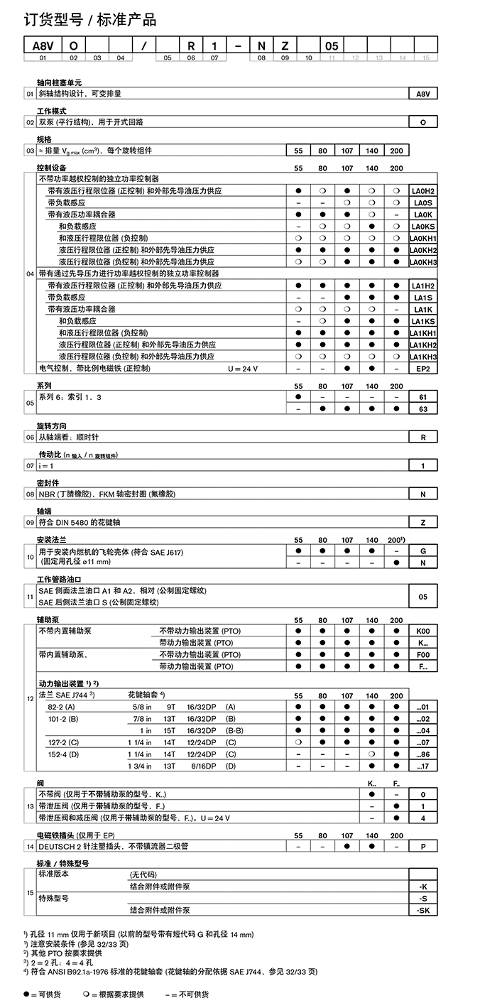
controlling device
Independent power controller without power override With hydraulic stroke limiter (positive control) and external pilot oil pressure supply With load sensing With hydraulic power coupler And load sensing And hydraulic stroke limiter (negative control) Hydraulic stroke limiter (positive control) and external pilot oil pressure supply Hydraulic stroke limiter (negative control) and external pilot oil pressure supply Independent power controller with overriding power control by pilot pressure With hydraulic stroke limiter (positive control) and external pilot oil pressure supply With load sensing With hydraulic power coupler And load sensing And hydraulic stroke limiter (negative control) Hydraulic stroke limiter (positive control) and external pilot oil pressure supply Hydraulic stroke limiter (negative control) and external pilot oil pressure supply Electric control with proportional solenoid (positive control) U = 24 V |
characteristic
|
– Variable double pump is equipped with two axial conical plunger rotating components with inclined axis design for hydrostatic transmission in an open circuit
– The flow rate is proportional to the input speed and displacement, and it changes steplessly from qv max to qv min(0) – The pump is suitable for mounting directly on the flywheel housing of a diesel engine – The auxiliary pump and the two oil circuits share one suction port – Powerful control program, which can realize different control and adjustment functions – Independent power controller – Built-in auxiliary pump with pressure relief valve, optional additional pressure relief valve – A variety of power output devices can be used to install axial piston and gear pumps – Outstanding power/weight ratio – Long service life |
– Variable double pump is equipped with two axial conical plunger rotating components with inclined axis design for hydrostatic transmission in an open circuit
– The flow rate is proportional to the input speed and displacement, and it changes steplessly from qv max to qv min(0)
– The pump is suitable for mounting directly on the flywheel housing of a diesel engine
– The auxiliary pump and the two oil circuits share one suction port
– Powerful control program, which can realize different control and adjustment functions
– Independent power controller
– Built-in auxiliary pump with pressure relief valve, optional additional pressure relief valve
– A variety of power output devices can be used to install axial piston and gear pumps
– Outstanding power/weight ratio
– Long service life
safety instructions
– The A8VO pump is designed for use in open circuits.
– Project planning, assembly and commissioning of the pump must be carried out by qualified personnel.
– Working line ports and function ports are only designed to install hydraulic lines.
– During and shortly after operation, the motor (especially the solenoid) may be at risk of burns. Take appropriate safety precautions, such as wearing protective clothing.
– The characteristics of the pump may vary, depending on the working condition of the pump (working pressure, oil temperature).
– Tightening torque:
-The tightening torques specified in this technical data sheet are all maximum values and must not exceed these values (maximum thread torque).
Observe the manufacturer's instructions for the maximum allowable tightening torque of the installation tool used!
-For DIN 13 fixing screws, we recommend a separate check of the tightening torque according to the 2003 version VDI 2230.
– Subject to the data and information provided here.
Installation Notes
safety instructions
During commissioning and operation, the axial piston unit must always be filled with hydraulic oil and discharge air. In the case of relatively long periods of inactivity, the above precautions should also be observed, because
The system may be drained through hydraulic lines.
The case drain cavity is internally connected to the oil suction cavity. There is no need to connect the case drain line to the tank.
Note the characteristics of the size 200 flushing fluid. (Port R4)
Under all working conditions, the oil suction line must pass into the position below the lowest oil level in the oil tank.
The minimum suction pressure of port S must not drop below 0.8 bar.
Installation location
The axis is horizontal.
Installation below the fuel tank
Installation below the fuel tank means that the pump should be installed below the lowest oil level of the fuel tank.


